What is this about?
One of my new addictions based on my woodworking hobby is CNCing. I use a Sorotec CL1007 machine with a QTC spindle (mainly for wood, but more and more for metal as well).
Sorotec provides excellent macros for their machines when you use Eding CNC as controlling hardware (and software). The macros provide you also an underlying workflow for Z-offset setting and tool height management.
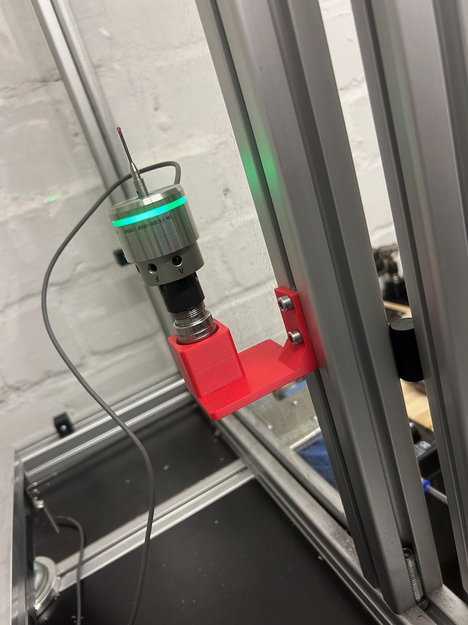
However, to improve my workflow, I added a 3DFinder sensor to the machine for easy X/Y work offset setting. I also wanted to use the 3DFinder to set the Z-offset of my workpiece, but this was harder than expected. The following article describes, how I changed the workflow, the macro and verified all measurements.
Prerequisites
- You need a fully installed Eding CNC based Sorotec machine
- Add the 3DFinder electronically in addition to your tool length sensor (how depends on your control configuration)
- Install the 3DFinder as described in the Sorotec specific manual. This includes also adapting the marcos (the special ones you can buy with 3DFinder are necessary)
- The 3DFinder needs to stay in one QTC tool holder, you need to align the runout in this holder and never remove the 3DFinder from this holder again (otherwise you will need to repeat everything)
- Be sure to very precisely and accurately do the calibration procedure of the 3DFinder software. This calculates a tip ball diameter offset based on your tip and machine. This offset is used in all calculations (X,Y and Z). If it is not accurate, all you 3DFinder measurements will lack accuracy.
What is the problem?
The XY offset setting works out the box pretty well. For Z you will need the tool height of the 3DFinder which is not easy to find out or even measure.
So the challenge we have is to find out the length of the 3DFinder at the switch point, very similar to finding out the length of the TLS when installing.
Why not using the Tool Length Sensor (TLS)?
Since we then have two switches with two springs, we would need to have a defined switching force for both sensors. The force of the 3DFinder would have to be higher since we would rely on the TLS to actually switch “first”.
However this is not guaranteed. My TLS and the 3DFinder have a very similar switching force, in fact the 3DFinder gets activated first – so not useful.
Solution
We will use the machine to measure the height of the sensor, but just indirectly. This is what you will need:
- a zero setter (something like this https://www.tschorn-gmbh.de/mechanical-zero-setters)
- a reference tool such as a measuring rod
- some special macro (see below)
We will first describe the necessary steps and explain later why this works.
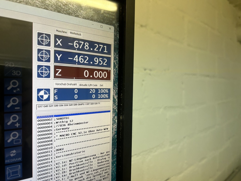
- Measure your reference tool using the Sorotec macro of your machine. Write down the tool length.
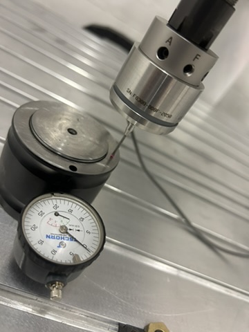
- Move over your zero setter. Zero the setter using a parallel rest or something similar
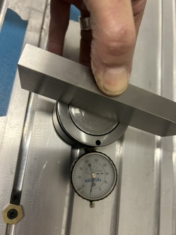
- Move your reference tool over the zero setter and move the Z axis of the machine so that the dial again shows “0.00”. Now the end of your reference tool has a defined height.
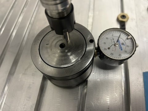
- Zero the Z work coordinates in Eding CNC
- Switch to the 3DFinder and move the tip over the edge (!) of the zero setter
- Start the special macro (if you copy the attached file: it is user 4 button)
- Now write down the Z work coordinate, which is printed in the log
The macro executes a piece of code similar to the code the 3D-Finder uses to find out Z0. It prints the work coordinate difference between Z0 and the “switch point” of the 3D-Finder.
To get the (virtual) length of the 3D-Finder, you will have to add this value to the length of the reference tool from step 1.
The result has to be stored in variable #4545.
Doing this precisely
It is a good idea to (1) and (6) multiple times and take an average of the respective measurements. This will also reveal any positioning errors in Z.
How does this work?
Usual Sorotec Workflow
The Sorotec workflow uses a relative tool length system to adjust various tool lengths for one job. Please note that out of the box the macros (and EdingCNC in the UI) use G92 for all offsets and not G54-G5x. Also the tool length table is not used and no build-in tool length compensation (G43).
Usually it works like this:
- You put your first tool ever into your spindle and click the TLS macro. This measures the tool length and stores it an an internal variable – but it does not change any work offset.
- You then use this tool to touch off the Z zero on your work piece – either manually or with the TLS. In both cases you will set the G92 offset of Eding CNC to the “zero height”.
Now you could start a job with the tool in the spindle as first tool.
When changing a tool:
- You change the tool and the new tool length is calculated. Then then tool length difference of old vs. new tool is used to move G92 up or down in Z direction, depending if you have a longer tool or a shorter tool.
As you can see, the reference position of the tool length is not used in the calculation, only the difference in tool length. This is also the reason that using the spindle nut as reference point (which is not accurate) works well. This “reference point” is only used as a safety depth when the TLS macro measures the tool length as maximum decline of the spindle (to avoid crushing in your TLS in case its empty).
And how does the Z calculation work then?
- By measuring the reference tool length, we determine our (kind of) virtual reference point.
- Then we align this reference tool with the known tool length to a fixed reference plane: by using the zero setter for the reference tool and the fixed (!) border of the zero setter for the 3DFinder. So we avoid the “two switches problem”
- By setting the work coordinate system to zero at the reference plane, we can use the CNC as measuring device
- When we are at the switch point, the 3DFinder is actually on the reference plane.
- The work coordinate Z now shows the difference of the reference tool length (which we know) and the 3DFinder length. So we can compute the 3DFinder length with the same virtual reference point as if we would have measured the 3D Finder on the TLS.
Tool Length Sensor Changes
In order to get reliable results, the tool length measurement has to be very accurate, which demands that we have to mount the TLS to the machine bed so that it cannot move.
I made several measurements to verify this. Without the TLS fixed on the bed (and being able to be moved for zero point adjustment), the variation can be around 0.1 mm.

The usual holder which enables you to pull the TLS to the workpiece (to define Z-Zero) is not accurate enough.
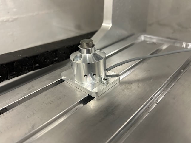
I created a mounting plate show in the pictures below. The TLS sensor activation point has to be updated after this very precisely using the Sorotec way of doing this.
I also changed the Sorotec marcos to allow for a X offset of the tool measurement position in the dialog. This is helpful for tools which do not fit with their blade on the TLSsses ” button” – such as my 40 mm face mill with three flutes, where you have to hit the TLS with the flutes.
Macro
Here is the macro (I remove the spindle warmup macro – never used it), I used to get the right length from the sensor. It is based on the original Z-touching-code, but does not change any offset in the machine.
;***************************************************************************************
Sub user_4  ; Helper function for getting the 3DFinder Z-Length
;---------------------------------------------------------------------------------------

	DlgMsg "3D-Finder Z-Längen Macro. OK um die Z-Differenz an der aktuellen X / Y Position zu ermitteln. Maximale Distanz Kugel zu Oberfläche ist 15mm."

	IF [#5398 == 1]	 ;OK

		#600 = #4548						; TEMP-Variable <- Geschwindigkeit zum Taster-Anfahren (mm/min)
		#601 = #4549						; TEMP-Variable <- Tastgeschwindigkeit zum Messen (mm/min)

		IF [#4544 == 0]						; Wenn Öffner (#4544 = 0)
			#185 = 1						; Fehler-Zustand (1= offen)
			ELSE							; Wenn Schliesser (#4544 = 1)
			#185 = 0						; Fehler-Zustand (0= geschlossen)
		ENDIF

		;-----------------------------------
		; Z Werkstückoberfläche antasten
		;-----------------------------------
		G38.2 G91 z-15 F[#600]					; Mit G38.2 Werkstück-Oberfläche antasten
		G90										; G90 -> Absolute distance mode
		IF [#5067 == 1]							; Wenn Sensor gefunden wurde
			G91 G38.2 z+2 F[#601]				; Langsam Taster zurückfahren zur exakten Ermittlung der Z Position
			G90
			IF [#5067 == 1]						; Wenn Sensor gefunden wurde
				#705 = [#5063 - #161]			; Werkstück-Oberfläche -> Position Z minus Radius-Offset des 3D-finder (#161)

				G01 G91 z+1 F[#600]				; [AP]
				G4 P0.1 						; Warten 0,1 Sek.

				G90								; G90 -> Absolute distance mode
				IF [#5068 == #185]				; Taster-Zustand prüfen ob Fehlerzustand #185
					msg "Sensor hat nicht zurück geschaltet"
					msg "Messung abgebrochen!"
					M30
				ENDIF

				msg "Messpunkt Z :  " #705
				msg "Diesen Wert zur Werkzeuglänge des Referenztools addieren und in #4545 speichern." #705

			ELSE
				msg "FEHLER (Z): Sensor hat nicht geschaltet"
				msg "Messung abgebrochen!"
				M30
			ENDIF
		ELSE
			msg "FEHLER: Sensor hat nicht geschaltet"
			msg "Messung abgebrochen!"
			M30
		ENDIF
	ENDIF
Endsub
